|
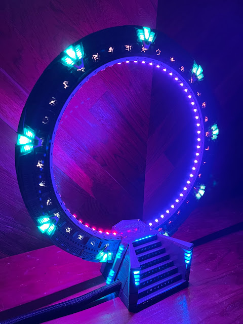
| The completed gate |
I share that first because I found myself telling that story a lot over the past year as I talked to various friends about the gate project, and also as a reminder in this social-media-highlight-reel-of-people's-lives world that there are also grittier down-swings behind the polished presentations. And while I generally do polish up my work before writing about it on this blog, I think it's important to acknowledge the full breadth of the journey.
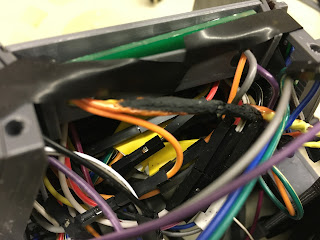 |
| Charred wires after the "smoke event" |
One of the most satisfying challenges to overcome in this project was the combination of having both addressable LEDs (my gate has 211 WS2812B LEDs) and sound, both controlled by a Raspberry Pi. While that might seem like a "so what?" kind of question, "everyone" on the internet said it couldn't be done. "They" said you can have a Raspberry Pi with sound, or you can have a Raspberry Pi with addressable LEDs, but you can't have both, because both the LEDs and sound want to use the same interface for communication, and interfere with each other. The only solution the internet proposed was to use a separate microcontroller (like an Arduino) to drive the lights, while the Pi drove the sound.

My other sort-of-new-to-me experience was designing some of my own printed circut boards, or PCBs. Previously I had made some tweaks to Boogle's PCB designs for his warp core and SG-1 gate, but this was my first time designing my own from scratch. Fortunately, these were not complicated.


The first was just a small board to sit on top of the Pi, with connections for the power supply coming into the board and going out to all the LEDs, along with a couple capacitors. The remainder were for mounting the LEDs. The WS2812B LEDs are very tiny (5mm square) and melt easily when trying to solder wires onto them. As noted above my gate has a total of 211 (though in fairness 61 of those are on a pre-made flexible strip, mounted inside the ring for the wormhole effect; so technically only 150 LEDs if I was hand-soldering them). That was, I decided, more delicate soldering than I felt qualified to tackle. Instead, I opted to design a series of custom PCBs for each specific area of the gate:
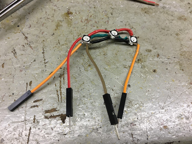
- a single LED (but with easier-to-solder connections, since it was on a tiny circuit board)
- a three-LED Chevron board, to use on the nine chevrons around the outside of the gate
- a 15-LED rear-window board
- Eight different stair PCBs, but all combined into one larger design so they didn't have to be ordered separately

I mentioned earlier I had a "smoke event" after assembling the gate. At first, I tried to fit the Pi and all the wiring into the base of the gate, as I'm under the belief that somehow that's what Glitch did in his original model. Well, I have no idea how he fit everything in there, because I couldn't. Well, I guess, I *did*, but in doing so smooshed some of my wires loose and caused a short, and some small amount of smoke. It was at that point I decided I would move the Pi and speaker into an external control box, to make the base less crowded. I learned the basics of using TinkerCad (a free online 3D modeling software) and designed a simple box in that.
It was also around this time that I did some math and realized my power supply was woefully under-rated for what I neeeded. Seperately from the smoke event, I think I actually burned out a small power adapter receptacle - all I know is it used to work, and then I turned a bunch of LEDs on, and then it no longer worked. Turns out that particular adapter was only rated for... 2 amps? I forget now, but it was definitely less than the possible 12 that I could draw with this many LEDs. Thus began my rabbit hole journey about power supplies and wire gauges, and redesigning my Pi's PCB with much thicker traces that could handle the necessary current.
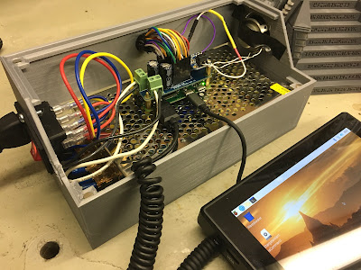 |
| Note the fancy orange power button on the left side of the box |
I still don't know for sure if it's a physically bad LED, or something wonky in the LED software package, or something else entirely. I had an issue where when I turned on the LEDs to the left of the staircase, the topmost LED would flash on for a split second, then turn off, while all the other LEDs remained on. If I turned the LED on by itself, it stayed on. If I did a strand test that turned on ALL the LEDs in the entire gate, the LED worked fine. If I coded it to turn red, green, or blue, it worked fine. If I turned on the side LEDs followed by turning on the wormhole, for instance, the single LED would flicker as if it was being told both to turn on and off at the same time. I'm pretty sure at one point I replaced the LED, though I'm not 100% sure so I can't completely rule out a hardware issue. In any case, it was baffling.
After many hours of troubleshooting and experimenting, I eventually tried setting the 4 LEDs in that side panel to a different color, and the top LED stayed on. So, for reasons I don't understand, that particular LED (#192 on my strand) simply can't be set to the particular color "Color(128,128,128)". Pretty much any other color and it'll work fine. I lost track how many hours it took me to figure that out.
The mystery of LED 192 was the last bug fix I worked through before publishing my finished code on GitHub and posting my make on Thingiverse, as well as this YouTube video of the completed gate, which I'll invite you to enjoy now, followed by some more photos of my gate under construction!
And a simple strand test:
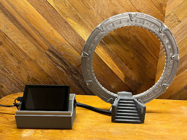 |
| Completed gate, with control box |


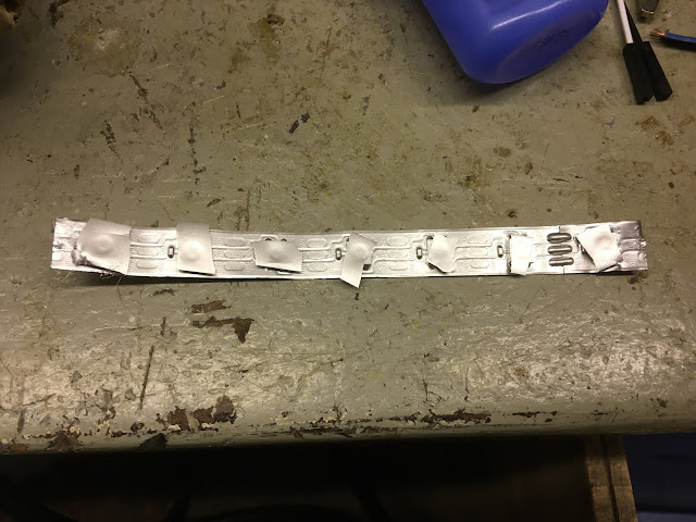 |
| Spray-paint test for "wormhole" inner LED strip |
 |
| Hand-soldering individual LEDs is fiddly!!! |


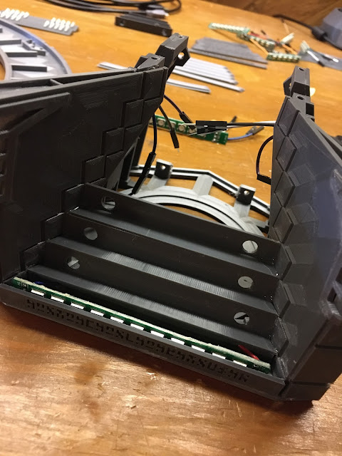

 |
| Back of the staircase |


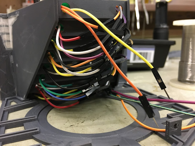
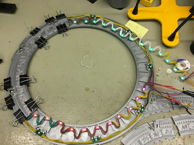 |
| Testing LEDs during assembly |