On August 17, 2017, my Dad texted me this link of a 3D printed Stargate with lights and movement:
https://www.thingiverse.com/thing:1603423
...thus inspiring my foray into the world of 3D printing. My Dad started 3D printing several years ago, and my friend Peter even longer ago than that, so while I'd seen printers in action before, for whatever reason it never held much pull on me. I'm sure partly that was because I already had enough other hobbies that I really didn't need "one more thing" on which to spend my time (and money). At least, until I saw that moving / light-up Stargate model.
I knew very little about 3D printing, except that prints could take an incredibly long time. Years ago I remember when a friend and I asked Peter to print a Star Trek: Deep Space 9 station, and after the first couple layers were down, he told us it would take another 24 hours to finish! That was basically the extent of my knowledge. (I chuckle as I write that now, because many of my prints nowadays take 24+ hours).
Over the past couple years as Dad has gotten into printing, he's created some gorgeous gifts for my Mom and also for my wife (for instance: a vase and roses for Valentine's Day, and a Beauty and the Beast jewelry container), and has offered to print things for me, too. Knowing practically nothing of the time and effort that it takes to get quality prints, I sent him a bunch of links for stuff I'd like, like tokens for one of my favorite board games, and paint racks for my miniature painting paints (unbeknownst to me until later, getting the paint racks to print successfully was no small endeavor in experimentation, and even once Dad had the right settings, it still took a day to print each rack). It's been so much fun watching Dad get into this hobby, and to see Mom cheering him on and sharing in the successes and not-so-successes.
After realizing that thingiverse.com held a treasure trove of Things I'd like to print, and feeling like I'd be taking advantage of my Dad if I kept asking him to print dozens and dozens of links, I decided I'd get my own printer. Besides all the other random things I wanted to print, my ultimate goal was to print that working Stargate. I asked Dad and other friends who had printers for their recommendations, and bought a Creality CR-10 in August 2018.
I came into the hobby rather naively (optimistically?), and grossly underestimated how much time 3D printing takes. I don't mean the printing itself, I mean all the behind-the-scenes overhead, like getting a level print bed (I'm convinced this is impossible), cleaning up from failed prints, replacing clogged nozzles, upgrading bits of hardware, configuring a print server (OctoPrint), or installing new firmware (which took the better part of a full day for me to figure out). When the printer is working, it's great! But there are just so many random things that come up that will suck away hours at a time. I wasn't prepared for that going into it, and definitely more than once thought "I'm never going to get this working." But Dad was always there to answer my questions and send me video tutorials and other links to help. And even over a year later I'm still asking him questions (see earlier comments about the firmware - Dad helped me a TON in navigating that experience!).
 |
| Each of these pieces took ~24 hours to print |
Back to the Stargate project itself. According to the webpage, it has 117 parts, and some I could see were very finely detailed, so I spent a few months getting the hang of printing in general (and tweaking my settings to get better quality prints) before starting in on a project that complex. I started experimenting with my first Stargate pieces in December 2018, opting to start with the most intricate first: the backside of the gate. Each piece took roughly 24 hours to print, then I'd write a number on it, change another setting or two and try again, keeping notes along the way so I could track what gave the best results. It took me roughly three weeks to fine-tune my settings for the high level of detail, with lots of "that's not quite good enough" results along the way.
After going through an entire spool of filament just on my experiments, I started printing parts "for real" sometime right before Christmas. Since I'd honed my high-precision settings already, printing the real pieces was fairly straight-forward, albeit time-consuming. The creator had written "total estimated print time: 112 hours," but I don't know what settings he used that could possibly print that quickly, since (for instance) each of my nine back-side-of-gate pieces took 12+ hours a piece. All told it took me three or four weeks to print everything.
 |
| Before trimming/cleaning |
 |
| After trimming/cleaning |
In reading and re-reading the original Stargate model page, I started looking at the builds other people had posted of their Stargate construction projects. One person's in particular stood out to me because he'd expanded upon the original design to add a web page interface for dialing the gate, a speaker to play sound effects, as well as designed a custom circuit board for the electronics. He also had a more thorough set of instructions. Based on his revised design, I started ordering electronics, which was it's own very stressful journey owing to the fact I haven't done anything electronics-y since 9th grade electronics class. I remember reading the lists of required parts and thinking, "I have no clue…" - what on earth is a PCB, LDR, or a Buck Converter? (The answers, I learned, are: "printed circuit board", "light dependent resistor", and something that changes voltage so you don't fry your electronics).
The PCB/printed circuit board came from a manufacturing facility in China, as did all the surface mount resistors, transistors, LEDs, and the like. Dad warned me in advance "are you sure you want to do that…" because as it turns out (I should say, as he already knew, and I was about to find out), the surface mount electronics are TINY!


By March 2nd, we'd connected together the Raspberry Pi, motor control circuit board, and Stargate PCB + buck converter, and connected the thing to the motors that would spin the gate and lock/unlock the top chevron; My Mom captured a video of me running a test program on the Pi that would just spin the motor, and me looking very excited and saying, "I drew a star!"
What on earth does THAT mean? It's an old family story - when my Dad was first getting into computer programming (in the early days of personal computers), he excitedly called my Mom into the room so he could show her that he'd drawn a star on the computer screen. My Mom lovingly said (or maybe just thought to herself), "so? If you give me a paper and pencil I can draw a star for you," until Dad explained more about how complicated the programming was, etc. Since then, it's been a comical story my parents tell whenever something looks easy but in fact took an incredible amount of time/effort. As was the case with drawing my "star"[gate].
The next day, I hit what I'll affectionally call one of my most frustrating "roadblocks" :

You might notice in the photo that the hole from the backside of one piece doesn't line up with the hole on the left side of the front piece. It's hard to explain in words, but if you look at this next picture, you can see the Stargate pieces glue together in an overlap pattern:


...and I'd superglued the overlap going the wrong direction. Had I used the original designs for these pieces, it wouldn't have happened, but because I wanted fewer visible seams on the gate I opted to use double-sized pieces that someone had posted; I never pieced together (pun intended) that these might need to be glued in a particular way. So, this was a major bummer, because it meant needing to re-print everything you see in that photo, and I was almost out of filament, and the company was out of stock of that color for the next month. Re-printing took over a week (and luckily I had just enough filament left!), and it gave me an opportunity to tweak my settings yet again to get a slightly better quality. Long after the fact, I thought of a way I easily could have worked around my gluing goof (aka, just using one or two normal-sized pieces to fix the off-set), but, I'm still happier with the end result of re-printing.
Between March and September I procrastinated, and I can cite a very specific reason why: I procrastinated because of my fear of failure. In this time period, I was having difficulty getting the gate symbols to spin smoothly - I could spin the ring by hand, but it would "stick" whenever I tried putting it on top of the motors (not enough torque, I guess). I was terrified of gluing everything together and then not being able to spin the symbols, and having to start over. My own perfectionism was my enemy.

Finally I spent an afternoon "just doing it": I bought and sprayed a plastics lubricant in the track, shaved off some plastic from the symbol ring clips that were catching on the edge of the track (the symbol ring is five pieces glued together in a ring, with small "clips" between pieces that help hold them together), filed down the backs of those joins, and got the whole thing to spin smoothly with the motors. Whew!!
Next challenge: the LEDs. There are nine chevrons around the gate, and each has three surface mount LEDs. I had an evening of despair after struggling for over an hour to solder together three LEDs and their wires onto the tiny LED holder I'd printed. I had no idea at the time how to test if my soldering was even good, and I learned the *wrong* way to test is to plug directly into 12V power. "Pop!" went the first LED. I nearly cried. I couldn't imagine taking over an hour to solder each of the chevrons. I texted my Dad and he said he had tools that would help (like self-closing tweezers and the fine point soldering iron he'd had me use before). Got together with him a couple days later and boy did having the right tools make all the difference. In only a couple hours at most, I'd soldered nine sets of LEDs, and also the two strings of LEDs for the ramp.


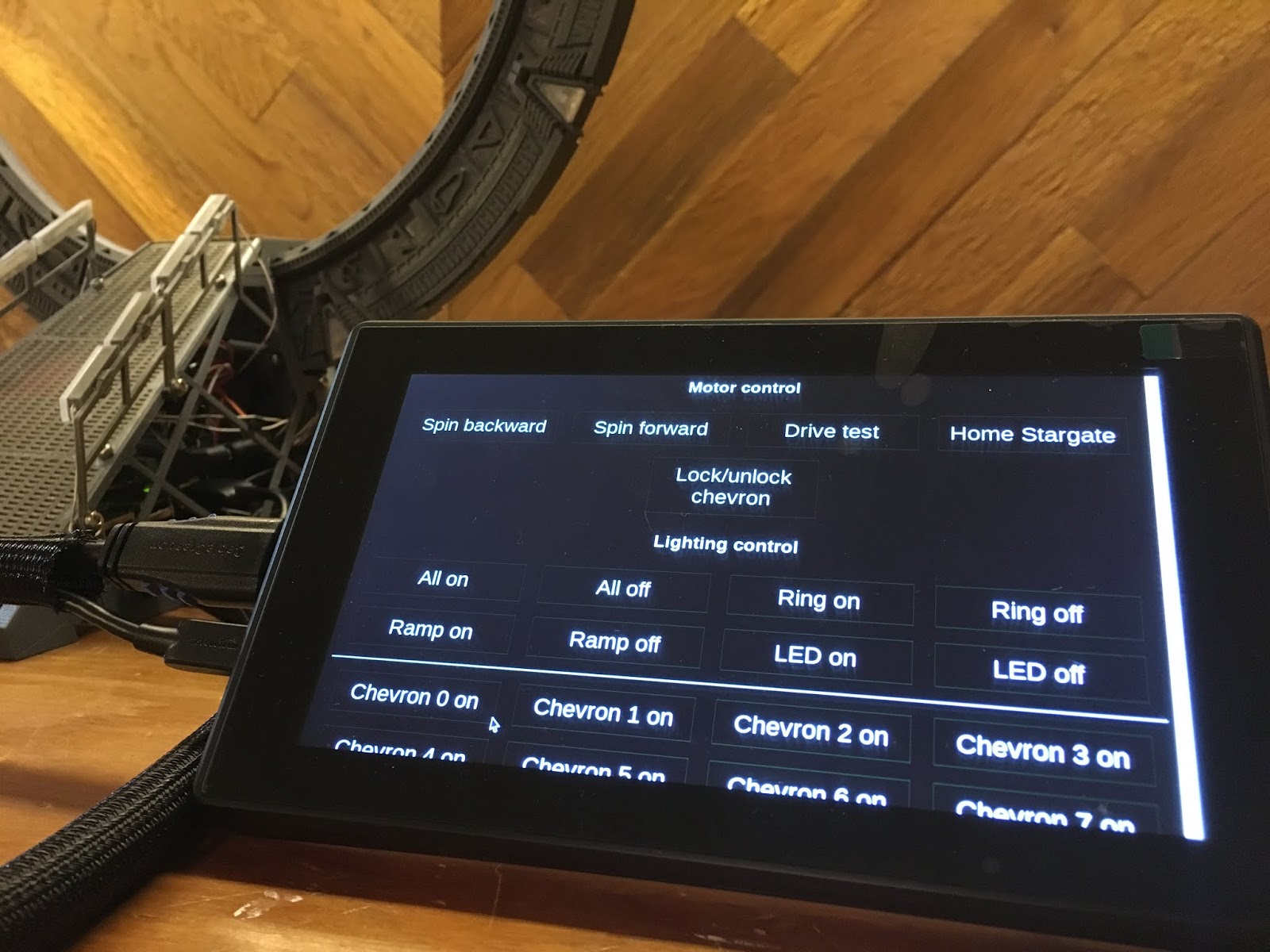
I'd printed LED holders someone designed for the Stargate that would position them exactly under each chevron, and twisted the wires so the LEDs lined up, then glued in place. Prior to gluing, I soldered each of the LED sets to longer wires that would run out the bottom of the gate and connect to power+ground (thanks to my Dad who supplied the super thin wire!), and test connected everything into the wires coming from the PCB. I also modified the webpage and server code so I could easily turn on/off each of the LEDs using a touchscreen I'd bought for the Raspberry Pi. This made it SUPER easy to figure out which light was plugged in where later on.
With all LEDs working, I began the exciting task of putting the wires and LEDs into their final position and gluing down the top pieces of the gate. I tested each as I went and surprisingly / thankfully ran into no issues.


That is, until I glued the last piece down and was faced with a bundle of wires sticking out the bottom of the gate. Around this time, I realized I'd never marked which two of the eleven wires were supposed to plug into 12V power. Oops. Paranoid about frying my LEDs now that everything was superglued, I managed to use a multimeter to figure out which wires I wanted (fortunately I hadn't glued the chevron covers on, so I could still stick a probe in to touch the LED wires inside each chevron). I then marked said wires with electrical tape so I wouldn't lose them again :)
After testing all the LEDs "one last time," I started final assembly of the ramp base, taking time to run all the wires nicely through the little wire holders, and of course finagling/weaving all the gate wires through the base.


Fully assembled, I booted the Pi and told it to "home" the gate - if you'll recall my construction goof earlier concerning the small hole, this allows an LED to shine through the gate to the light sensor / LDR on the other side, but only when a particular symbol is lined up; that way the software knows the gate is at "home."
As the gate spun and spun, I discovered two issues. The first is that, despite all my efforts for a smoothly spinning track, the gate was catching in two specific spots. My worst fear. My best guess is I didn't file/smooth out the bottom side of the track enough, and/or that I hadn't trimmed off the printing brim from the gear teeth. I took the gate off, sprayed a ton of plastic lubricant in through the bottom opening and manually spun the ring to get it all around; I also propped the gate up slightly off its base, just a few millimeters, so it didn't sit as tightly on the gear. Between those two remedies, the gate began to spin fully around without catching.
But it kept spinning. And spinning. And never found "home". This was my second issue: I'd assembled the LED and LDR pieces on the wrong side of the gate, and because the see-through-hole was offset from center, the light was in the wrong place and couldn't shine through. It wasn't a huge deal, but still tedious to remove the gate again, unscrew/move/re-attach/re-wire the LED and LDR pieces. Even after lining everything up correctly, though, the LED I had wasn't powerful enough to trigger the sensor, so I went back to my local Radio Shack (whom I lovingly call "Dad") and he had a brighter LED he gave me, which worked more gooder.
Had a couple more issues come up, like the motors spinning in reverse direction (easily fixed by swapping two wires around), and the top chevron not moving up and down smoothly (eventually "fixed" by spraying in a TON of that plastic lubricant), but otherwise, at long last, the gate was finished! I took a video and sent it to my parents, and also of course grabbed Alissa and said "come see! Come see!!"


I'm really proud of how this turned out. I enjoy projects (like this one) that are at the edge of my current abilities; I had a lot of confidence on the software side, but not a lot / any experience on the electronics side of things, but with my Dad there to guide me, it became much more manageable. I've learned a LOT from where I started, and am feeling more confident to tackle other 3D printing + electronics type projects (next up: a Star Trek Next Generation warp core). Things I worried about early on (like the seams showing between pieces of the ring) aren't nearly as visible as I thought they'd be. And I was able to make modifications to the code that I'll publish back to Thingiverse, that might help a future builder when they build their Stargate. If I do say so myself, this thing's pretty darn cool.
Lastly, if you're wondering how much it cost... I'll admit the number surprised me. Here's a rough breakdown:
- Filament: three rolls at $18 each, plus a couple other colors that I only used a bit of, so let's say $60
- Raspberry Pi 3 B+: $56
- Motors, motor circuit board, other electronics from Adafruit.com: $80
- Touchscreen for Raspberry Pi: $80
- HDMI cable: $8
- Power adapter: 2 for $14, so $7
- Printed circuit board from China: $20 ($2 for 10 boards, and $18 shipping…)
- LEDs, transistors, resistors, and other various electronics from LCSC: $21
- Superglue: $5
- Wires, tools, solder, buck converter, other electronics and tools: free from the RadioShack of Dad
Grand total: $337. (Shhh don't tell Alissa! :)
11 comments:
Absolutely FANTASTIC!!! Such a good learning experience and great bonding time between you and Dad. Now, you guys should go exploring other worlds!
Observation and Question: I didn't see the TON of plastic lubricant in your price list. Do you have a total for actual time spent on project?
Oops, you're right, lubricant was another $7 for the can.
I lost track long ago of how many hours. Many.
Very impressive! I am a fan! I am currently working on a similar project myself. If you are interested you can check it out here:
https://stargate.datarommet.com
Very impressive Kristian!!! That looks amazing!
Fantastic job and write up. I've had this on the back burner since Dec 2018 and im finally printing all the parts and have had everything Boogle made to work with the pi. Had a fewquestions if you dont mind.
When wiring the LEDs in the gate, is it a single 12V rail wire around the whole perimeter and then ground wires for each chevron out the bottom?
When connecting all the leads to Boogles control PCB, did you solder the wires to the pcb or did you use headers to keep them removable? In all the photos between yours and his I cant get a clear look at how those connections are made with all the wires all over it.
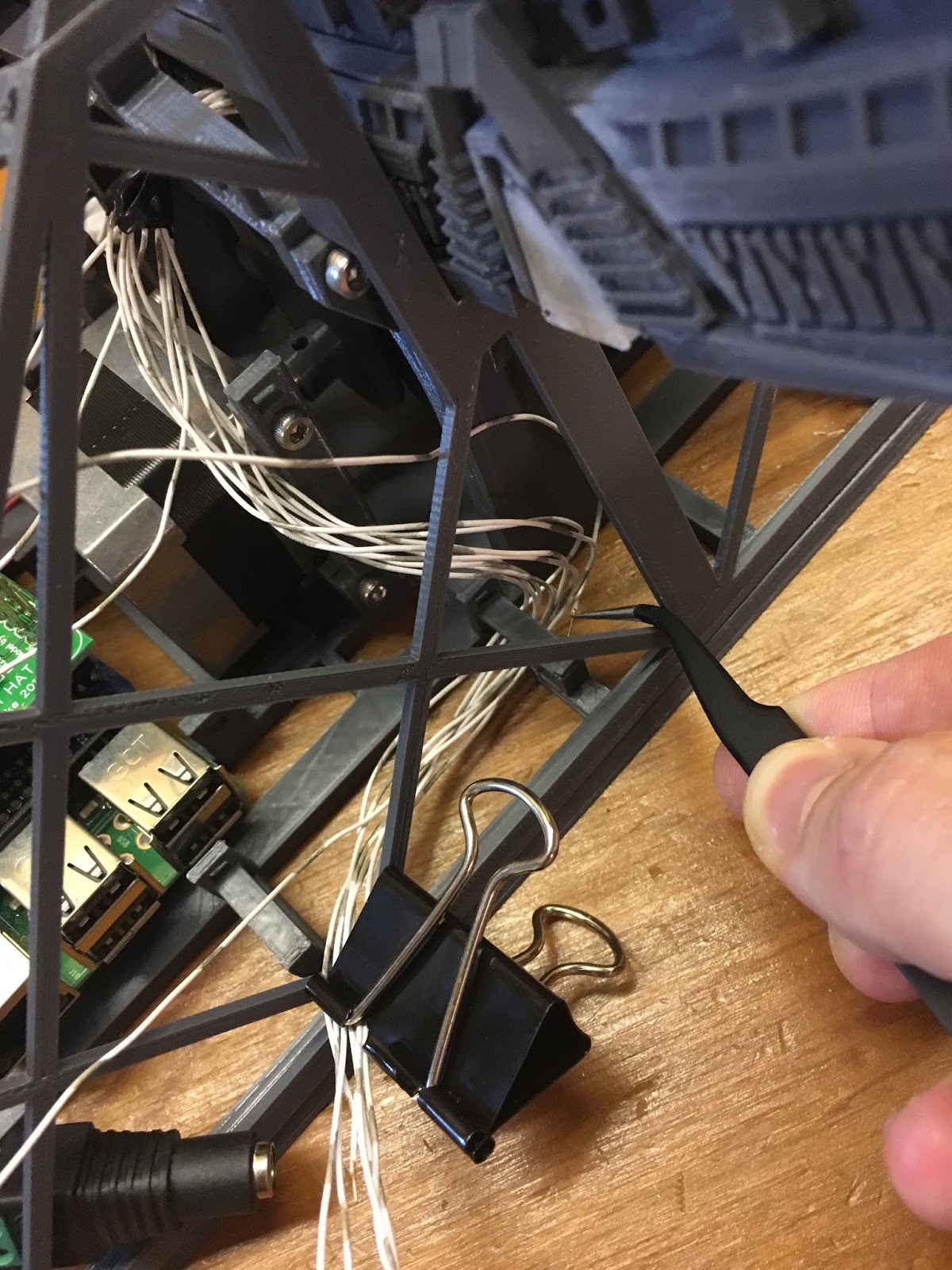
Am I right in assuming the shots with binder clips are you holding segments together for testing before final gluing?
Again, love how yours turned out and this write up will help a TON. Even plan on using your modded code for its extra functionality.
Hi James, thanks for reading and commenting! I'll confess it's REALLY gratifying to hear my write-up was helpful!
Some answers:
Regarding the 12V wire around the gate: I had trouble fitting the wire through the space around the top chevron (due to the locking/unlocking mechanism), so I actually ran a separate 12V wire for each side of the gate. But, if you're able to make it fit, yes, one 12V wire around the entire gate would be the way to go. And then yes, an individual ground wire for each chevron, coming out the bottom. PS, make sure to clearly mark which wires are 12V, so you don't end up with 11 wires sticking out the bottom of your gate after gluing everything together and having no clue which was which (not that I speak from personal experience or anything...)
At the risk of being overly verbose: my Dad suggested (and I followed his advice) soldering all nine sets of three LEDs first, with wire tails coming off each end; then I twisted each chevron's LEDs into a little loop and super glued to the LED holders from https://www.thingiverse.com/thing:2795518. (there's a photo of this in my blog post). I test-placed one chevron at a time (starting at the top), and then measured the length of wire I needed for both ground out the bottom of the gate, and 12V to the next chevron in the circle, and soldered that way. Once all the solders were done I went back and started glueing things in place, again starting at the top.
I used male/female jumper cables (a couple inches long) to connect to the PCB, so I could detach the gate *somewhat* easily if I needed to. That said, it's difficult enough to attach/detach the gate it's unlikely I ever will, but, I "could". The ground and 12V wires from the gate then go into the female jumpers and I used a lot of electrical tape to keep 'em there :) You could use headers instead of jumpers, BUT, the space under the ramp is very limited so I'd suggest using the short jumpers instead. I'm sure you already noticed, but just because it wasn't immediately obvious to me I thought I'd point out too that Glitch's base has some nice cable-management slots built into the model.
Yes, binder clips are for test-fitting, particularly the spinning inner ring. Oh my goodness what a stressor that was. And then I also used binder clips to hold pieces while the glue dried. I used superglue but I think if I were to do it again, I'd use hot glue, to make the bonds slightly less permanent.
I'm excited to see how yours turns out! If you want to add even MORE to your gate, Hummerfresse in Germany took my write-up and also added a 12V blue LED strip inside the ring for a wormhole effect: https://www.thingiverse.com/make:777042. I asked him about it and he said he added the LED strip in parallel with the ramp LEDs, though, had to change the ramp-LEDs' SMD transistor "to another with min. 500ma.... for example an BD139." He notes it's "tricky soldering a normal transistor to the smd pads. but it works." So, do with that information what you will! I'm hoping to add it to mine someday.
Any more questions, feel free to ask! Otherwise, best of luck, and keep an eye in a few months, as I'm working on Glitch's Atlantis gate now and plan on posting a very similar set of documents for that one. Working on that side-by-side with Boogle's make of the St:TNG Warp Core, not sure which one I'll end up finishing first.
Oh man the Atlantis one would be awesome. I want to make that too but it seems like Glitch lost interest in ever finishing the code for the electronics. I even have a strip of neopixels laying around from an aborted Nanoleaf clone project that I'd love to put to use. Consider your blog bookmarked!
Great, I just want to ask because I'm building the same star gate, which board is connected to the razpberry pi (the middle one)? And I would also like to ask what are the boards that are connected to the top. well thank you
Hi Samuel, check out my in-depth documentation here: https://github.com/jeremygustafson/WorkingStargateMk2Raspi
In particular, the answer to your question is:
"The Adafruit Motor HAT will be stacked directly on top of the Raspberry Pi, with Dan's custom Stargate HAT/PCB then stacked on top of the Motor HAT."
Good luck with your build! Feel free to reach out with any other questions. I do know some of the Pi software has changed since I wrote my directions, I'm hoping to get those updated "when I have time..."
Hello Jeremy,
I have run into a few problems with the software. I get a "Failed to load overlay i2s mmap"
and also when loading the dialing screen i get " This site cant be reached, 127.0.0.1 refused to connect" which if I press a dialing sequance i then get "could not send dialling sequence" as a pop up in Chromium. I have tried numerous versions of linux and are using desktop versions. Any help would be appreciated
Hi @terry, can you send me an email, jeremy at jeremygustafson dot net, and I'll follow up with you. This sounds more complicated than I think I can answer through blog comments :)
Post a Comment